1998 Honda Civic Under Hood Fuse Box Diagram
Honda Civic (2006-2011) fuse and relay
The 8th generation Honda Civic was produced in 2006, 2007, 2008, 2009, 2010, 2011. During this time, the model has been restyled. In this publication you will find a description of the Honda Civic 8G fuses and relays with box diagrams and locations of the main electronic control units. Highlight the cigarette lighter fuse.

Contents
- 1 Passenger compartment
- 1.1 Location
- 1.2 Fuse box
- 2 Engine compartment
- 2.1 Location
- 2.2 Fuse box 1
- 2.3 Fuse Box 2
- 3 Users Manual
Passenger compartment
Location
Diagram
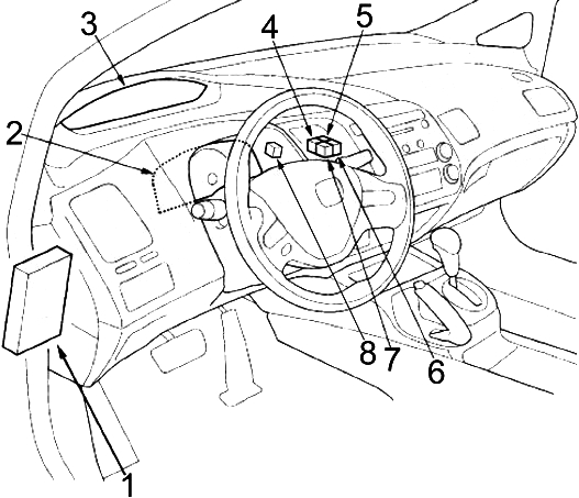
Designation
- Fuse box
- Instrument cluster (tachometer)
- Instrument cluster (speedometer)
- except GX: Relay for socket outlet in center console
Hybrid: Front Outlet Relay
GX: Starter control relay - except GX: Relay, front socket
Hybrid: Relay for socket outlet in center console
GX: Center console socket relay - GX: Front outlet relay
- GX: Relay for injector control unit
- SL ('09 -'11): Fog Light Relay
Diagram

Assignment
- '08 -'11: Tire Pressure Monitoring System (TPMS) Control Module
- Audio and navigation control unit
- Electric power steering (ESP) control unit
GX: Injector control unit - Coupe: Audio amplifier
- Airbag control unit
- '09 -'11: USB Connector Control Box
- Heater and air conditioner control unit
- Immobilizer control unit
- '09 -'11: Handsfree Control Unit (HandsFreeLink)
- Sedan: Audio System Amplifier
Diagram

Designation
- '09 -'11: USB Connector Control Box
- Hybrid: Powertrain Control Module (MCM) Relay # 1
- Hybrid: Powertrain Control Module (MCM) Relay # 2
- '07 -'10: XM receiver (if navigation is available)
- Hybrid: Powertrain Control Module (MCM – Motor Control Module)
- '09 -'11: Handsfree Control Unit (HandsFreeLink)
Fuse box
To access the fuse box, turn the lock counterclockwise and remove the steering column shield.
Step 1
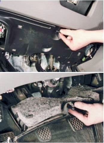
Step 2

Diagram

Protected components
| 1 | 7,5A Illumination of the control panel for electric mirrors, power window relays |
| 2 | 15A except Hybrid: Fuel pump, CMP sensor A, Engine control unit (ECM / PCM), Immobilizer control unit |
| 15A Hybrid: Engine and Transmission Control Module (PCM), Fuel Pump (Engine Control Module (PGM-FI) Relay # 2), Immobilizer Control Module | |
| 3 | 10A Alternator, Engine Control Module (ECM / PCM), EVAP (Mass Air Flow (MAF) Sensor) |
| 10A DC-DC converter, electrical load sensor (ELD), petrol vapor recovery (EVAP), mass air flow (MAF) sensor, engine and transmission control unit (PCM), brake pedal position sensor, secondary heated oxygen sensor (HO2S) | |
| 4 | 7,5A Control unit and pressure modulator ABS or VSA, multi-axis acceleration sensor (VSA), electric power steering (ESP) control unit |
| 5 | 15A Coupe: Audio amplifier |
| 15A Heated front seats, heated seat relay | |
| 6 | 20A Front fog light |
| 7 | 7,5A Tire Pressure Monitoring System (TPMS) |
| 8 | – |
| 9 | 7,5A Front passenger seat occupied detection system (ODS), front passenger airbag deactivated indicator, airbag control unit |
| 10 | 7,5A Instrument cluster (tachometer), power window control unit (coupé), reversing lamp switch (M / T), selector lever lock solenoid (A / T), body electronics unit (MICU), tire pressure monitoring system (TPMS), monitoring module Battery Status (BCM) (Hybrid), Interface Box |
| 11 | 10A Airbag control unit |
| 12 | 10A Right headlight (high beam) |
| 13 | 10A Left headlight (high beam) |
| 14 | 7,5A Instrument panel illumination, interior illumination, front passenger airbag deactivated indicator |
| 15 | 7,5A Parking lights, license plate lighting |
| 16 | 10A Right headlight (low beam) |
| 17 | 10A Left headlight (low beam) |
| 18 | 20A High beam, body electronics unit (MICU) |
| 19 | 15A Side lights, body electronics unit (MICU) |
| 20 | 7,5A Rear fog light |
| 21 | 20A Low beam, body electronics unit (MICU) |
| 22 | 7,5A Hybrid: A / C Compressor Actuator |
| 23 | 7,5A Starter signal, engine and transmission control module (PCM) |
| 24 | 20A Sunroof |
| 25 | 20A Central locking, body electronics unit (MICU) |
| 26 | 20A Driver's power window (power window control unit) |
| 27 | 20A Heating and air conditioning system |
| 28 | 20A Center console socket |
| 15A Center console socket | |
| 29 | 20A Front outlet (cigarette lighter) |
| 15A Front outlet (cigarette lighter) | |
| 30 | 20A Front passenger window, sunroof control unit (coupe) |
| 31 | 20A headlight washer |
| 32 | 20A Rear right power window, sunroof control unit |
| 33 | 20A Rear left power window |
| 34 | – |
| 35 | 7,5A Audio system, front socket, center console socket, audio amplifier (coupé), hands-free system control unit (HandsFreeLink), ignition switch, body electronics unit (MICU), Interface Box |
| 36 | 10A Heater and air conditioning control panel, electric mirrors, air recirculation system, air conditioning compressor clutch relay, heater relay, heated mirror relay, heated rear window relay, cooling fan control relay, cooling fan relay (air conditioner diode), AHB buzzer (Hybrid) , servo block (Hybrid) |
| 37 | 7,5A Daytime running lights, body electronics unit (MICU) |
| 38 | 30A Wiper, body electronics unit (MICU) |
Cigar lighter (power outlet) fusesare the fuses #28 (Rear Accessory Socket) and #29 (Accessory Socket)
Relays are installed in the upper part of the unit.

Relay
- R1 – Power Window
- R2 – Fuel Pump (PGM-FI Main 2)
- R3 – Starter
Engine compartment
Location
Diagram

Designation
- Control unit and pressure modulator ABS or VSA
- Hybrid: Fuse Box 2
- Engine and automatic transmission control unit (ECM / PCM)
- Hybrid: Servo block
- Fuse box 1
Fuse box 1
Diagram
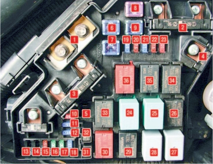
Circuits protected
| 1 | 100A Battery |
| 70A Electric power steering (ESP) control unit | |
| 2 | 50A Ignition lock |
| 80A except Hybrid: Fuses (box in the passenger compartment): 5, 6, 7, 27, 28, 29, 31 | |
| 80A '06 -'07 (Hybrid): Fuses (box in passenger compartment): 5, 6, 7, 27, 28, 29, 31 | |
| 60A '08 -'11 (Hybrid): Fuses (box in passenger compartment): 5, 6, 7, 27, 28, 29, 31 | |
| 3 | 30A Control unit and pressure modulator ABS or VSA |
| 30A except Hybrid: Control unit and pressure modulator ABS or VSA | |
| 30A Hybrid: ABS control unit and pressure modulator | |
| 40A Hybrid: Control unit and pressure modulator VSA | |
| 4 | 50A Fuses (block in the passenger compartment): 18, 19, 20, 21 |
| 40A Fuses (block in the passenger compartment): 24, 25, 26, 30, 32, 33 | |
| 5 | 40A Hybrid: Servo block |
| 6 | 20A A / C fan relay, A / C fan |
| 7 | 20A M / T: Cooling fan relay, cooling fan |
| 30A A / T: Cooling fan relay, cooling fan | |
| 8 | 30A Sedan: heated rear window relay, heated rear window |
| 40A Coupe: heated rear window relay, heated rear window | |
| 9 | 40A Heater relay, heater |
| 10 | 10A Hazard warning system, body electronics unit (MICU), instrument cluster (speedometer), instrument cluster (tachometer) |
| 11 | 15A Air / Fuel Ratio (A / F) Sensor # 1, Engine Control Module (ECM) / PCM), Vent Shut Solenoid (Hybrid) |
| 12 | 15A Stop lamps, engine and automatic transmission control module (ECM / PCM), horn, body electronics unit (MICU) |
| 13 | 15A Hybrid: Rear ignition coils |
| 14 | 15A Hybrid: Front ignition coils |
| 15 | 7.5A A / C blower relay, oil level sensor |
| 16 | – |
| 17 | 15A Coupé: Audio amplifier |
| 18 | 15A except Hybrid: Ignition coils, engine control unit (ECM / PCM) |
| 20A Hybrid: Ignition coils, engine and automatic transmission control unit (PCM) | |
| 19 | 15A Crankshaft Position (CKP) Sensor, Camshaft Position (CMP) Sensor B, Automatic Transmission Control Module (ECM / PCM), Throttle Valve Relay (ETCS), Injectors, Engine Control Module Relay (PGM-FI # 1 / PGM-FI # 2 (fuel pump)) |
| 20 | 7.5A A / C compressor clutch relay, A / C compressor clutch |
| 21 | 15A Throttle valve relay (ETCS), engine and automatic transmission control module (ECM / PCM) |
| 22 | 7.5A Interior lighting, luggage compartment lighting, electric auxiliary coolant pump (Hybrid) |
| 23 | 10A Audio system, diagnostic connector (DLC), instrument cluster (speedometer), instrument cluster (tachometer), alarm, immobilizer control unit, body electronics unit (MICU), powertrain control unit (MCM) (Hybrid), condition monitoring module Batteries (BCM) (Hybrid), Handsfree Control Unit (HandsFreeLink) |
| 24 | Heated rear window relay |
| 25 | Heater motor relay |
| 26 | A / C condenser fan relay |
| 27 | Engine cooling fan control rele |
| 28 | Rear wiper relay |
| 29 | PGM-FI injection override relay |
| 30 | Ignition coil relay |
| 31 | Iiodine of the fan motor of the engine cooling system |
| 32 | Air conditioner condenser fan motor diode |
| 33 | Air conditioner clutch pele |
| 34 | Engine cooling fan relay |
| 35 | Throttle actuator relay |
| 36 | PGM-FI MAIN Injection Main Relay |
Fuse Box 2
Diagram
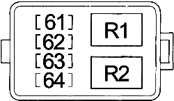
| No. | A | Assignment |
| 61 | 10 | BCM Module, Motor Control Module (MCM) Relay No.2, Servo Unit |
| 62 | 7.5 | BCM Module, Motor Control Module (MCM) Relay No.1 |
| 63 | 15 | Servo Unit |
| 64 | – | – |
| Relay | ||
| R1 | Auxiliary Electric Water Pump | |
| R2 | Fuel Pump | |
Users Manual
Need more information about service Honda Civic 8G – study the Users Manual. Or ask your questions in the comments.
We use cookies on our website to give you the most relevant experience by remembering your preferences and repeat visits. By clicking "Accept", you consent to the use of ALL the cookies.
Source: https://fuseandrelay.com/honda/civic.html
Posted by: profffoot.blogspot.com